Introduction
The aim of this project is to design a digital clock with the help of the hardware descriptive language as VHDL and simulate the design with the help of an FPGA board. the FPGA board used here is by Digilent named Nexys 4 DDR which works on Artix-7 FPGA chip. The digital clock is a clock that will display minutes and hours on the 4-seven segment LEDs on the board. The clock can be reset with the help of a reset button. For this project, a Different number of digital components are used as counters, decoders, and encoders, clock dividers. The codes used for this project can be found on GitHub
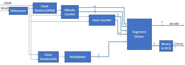
Experimental Procedure
Design Process
While working on a big project like this in VHDL the task should be broken down into multiple small blocks for simplicity and ease of work. This is called Divide and Conquer, which also follows the top-down design principle. So, for that, I designed a flowchart that can flow throughout the design process to get optimized results.

Debouner
In this block, I aim to filter out the noise that is created while changing the state of reset. This can be done by. This block will look for changes in the input signal and store them. With the help of the XOR gate, the current button state and stored button state are checked for a state change. And if so, the state is changing the new state will be constant.
Clock Divider
Minute Counter
This component will have a clock input frequency of 1Hz. At every clock event, the value of the counter will be incremented. the value of the counter will reset as it reaches 59, at the same time the value of the minute counter will be incremented. As the minute counter reaches 59 it will send the signal to the hour counter. If the reset signals go high in between the counters will reset. Along with this, the value of the minute counter will constantly be updated to the segment driver.
Hour Counter
In this component the input from the minute counter will be counted, at every event, the hour counter will be incremented. As the hour counter reaches 12 it will reset. If the reset signal gets high in between the counter will reset. Besides this, the value of the counter will be constantly updated to the segment driver.
Clock counter
This component gets an input clock signal of 100Hz from a clock divider. At every clock event, the counter is incremented till 4 and it resets. The value of the counter is updated regularly to the segment driver.
Segment driver
This part of the process has 4 cases to run four 7 segment displays. the signals from the clock counter help switch each case at a regular time interval of 0.04 seconds. Along with this, it will also assign the digit to be displayed on the 7-segment from the hour and minute counter.
BCD to 7 segment
Top file
Testing
To test this design a testbench code was written.


Conclusion
As a conclusion of this project, a digital clock was engineered and tested in VHDL. I was simulated on Nexys 4DDR board. . The task was done by breaking the complete task into small blocks and solving and programming each block. A corresponding testbench was also created to test the correctness of the design. If given more time I would like to work on implementing more features and multiple time clocks and alarms.